



-

About Flexfilm 2
-

Getting Started 10
-
Core Fundamentals 10
-
-

Orders & Support 83
-
Shipping 10
-
Dealer Rewards 13
-
Ordering & Account 7
-
Pre-Cut Patterns 2
-
General 9
-
Warranty 6
-
Billing & Tax 3
-
Route Package Protection 2
-
Returns & Refunds 2
-
Shop Pay 2
-
Training 1
-
Dealer & Installer Program 4
-
Selling & Quoting 9
-
Marketing & Growth 8
-
Business Operations 5
-
-

Installation Resources 19
-
Architectural 4
-
Automotive 5
-
General 10
-
-

Architectural Window Film 55
-
Safety & Compatibility 18
-
Ownership 2
-
Fundamentals 16
-
Buying Guides 4
-
Performance & Privacy 6
-
Product Guides 9
-
-

Automotive Window Film 40
-
Installation & Ownership 18
-
Product Guides 11
-
Legal & Compliance 3
-
Buying Guides 8
-
-

Tools 10
-
Cutting & Prep 3
-
Application 3
-
Measurement & Layout 2
-
Specialty 2
-
-

Plotters 8
-
Ownership 6
-
Buying Guides 2
-
-

FlexCut Software 25
-
Account & Licensing 5
-
Getting Started 10
-
Troubleshooting 2
-
Using FlexCut 8
-
-

Paint Protection Film (PPF) 10
-
Ownership 3
-
Fundamentals 4
-
Product Guides 3
-
-

Surface Coatings 13
-
Product Guides 7
-
Fundamentals 3
-
Ownership 3
-
Plotter Setup


Plotter Setup
The software requires at least one plotter to be installed. If no plotter is installed, the software will prompt you to install one.
If you need to add another plotter or change the connection settings for an existing one, go to File in the main menu, then select Setup Plotter...
To install a plotter, click the “Add...” button, select the model from the list, and click “Install...”
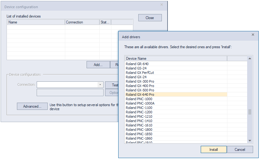
After adding the plotter, select the connection type in the Device Configuration section.
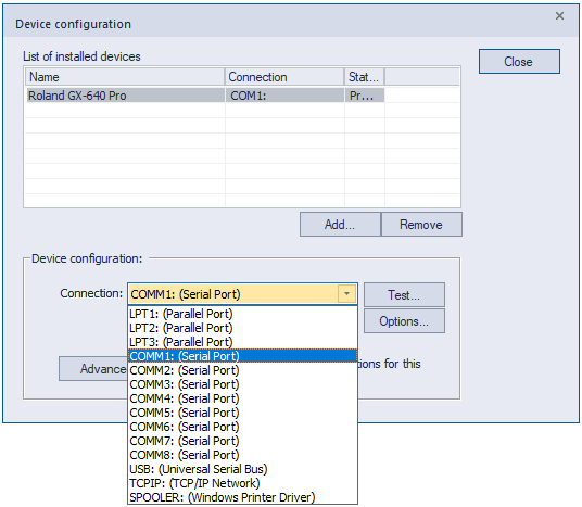
Most modern plotters use a USB connection. However, many second-tier models may still require selecting a COM port, even if the plotter is connected via USB.
To modify the connection settings, select the plotter from the list and click “Options.”
USB Connection Type
You can only choose a device that appears in the USB devices list. Click the “Detect... >>” button and locate your plotter in the list.
If you have a well-known plotter brand such as GCC, Roland, or Graphtec, you will see the manufacturer's name in the Vendor ID column. This may not display the full model name, but the manufacturer should be easy to recognize.
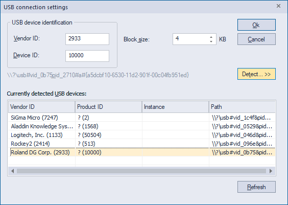
For second-tier plotters that often use older chips from other well-known brands, the name shown under Vendor ID can vary. The most reliable way to identify the plotter is to turn it off and watch which device disappears from the list.
It is also common for a plotter to have a USB port but still require the COM connection type because a USB-to-COM adapter is built into the plotter.
COM Connection Type
With a COM connection, you can change the transfer speed and certain settings such as parity. It is strongly recommended that you refer to your plotter's manual before changing these settings.
TCP/IP (Network) Connection Type
Prerequisites
- Your PC and plotter are connected to the same network.
- You have already tested the plotter using a USB or COM connection and confirmed that it works.
Open the Command Shell by pressing Win + R, typing cmd, and pressing Enter.
A black command-line window will open. You will use this while setting up the network connection between your PC and the plotter.
Step 1: Configure the Plotter's Network Settings
Set the network interface IP settings on your plotter. The IP address, subnet mask, and gateway should match your network configuration. Refer to your plotter's manual for instructions on configuring its network interface.
If you do not know your network gateway and subnet mask, type ipconfig /all in the Command Shell and press Enter.
This will display the network adapters installed on your PC. Usually there is only one active adapter, but there may be more. Locate the adapter that is connected to your network.
The IP address will often begin with 192.168, although this is not always the case, particularly on Wi-Fi networks.
Note the Default Gateway and Subnet Mask shown for that adapter and use them when configuring the plotter's network interface.
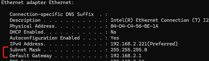
For example, if your office network is 192.168.2.0, you might assign the plotter the IP address 192.168.2.250.
The gateway in this example would typically be 192.168.2.1, and the subnet mask would be 255.255.255.0.
Make sure the IP address you assign to the plotter is not already being used by another device on the network.
To check whether the IP address is already in use, type:
ping 192.168.2.250If the result is “Request timed out”, the device at that IP address did not respond, which generally indicates that the address is available.
If you receive a response similar to:
Reply from 192.168.2.250: bytes=32 time<1ms TTL=128the IP address is already in use and you should choose another one.
Step 2: Connect the Plotter to the Network
Connect the plotter to your network switch or wall Ethernet port using a network cable.
Do not connect your computer directly to the plotter using the network cable.
In the Command Shell, type:
ping 192.168.2.250Since the plotter is now connected to the network, it should respond to the ping.
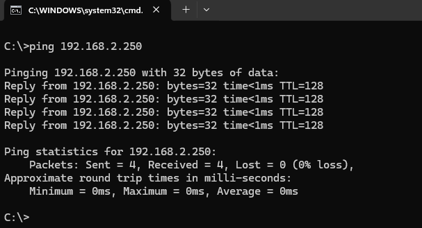
If the plotter does not respond, review the plotter's network interface configuration and your network settings. You may need to contact your system administrator for assistance.
If the plotter responds, the network connection has been established and you can proceed with the TCP/IP setup in the software.
Step 3: Configure TCP/IP in the Software
In the software, open File > Plotter Setup... from the main menu.
Select the plotter, then change the Connection setting to TCP/IP.
Click “Options”, select “By IP Address”, and enter the IP address assigned to the plotter.
Using the example above, the IP address would be: 192.168.2.250
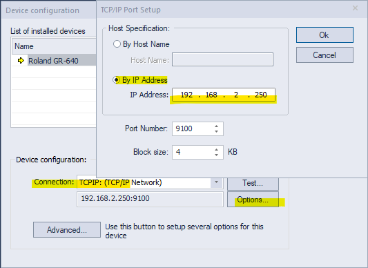
Click “OK” to save the settings, then click “Test...”.
If the setup is correct, you should receive a message confirming that the connection was successful.
You can now send cut jobs to the plotter over the network.
If you experience problems connecting your plotter, please contact our tech support team.